How to draw an architecture diagram
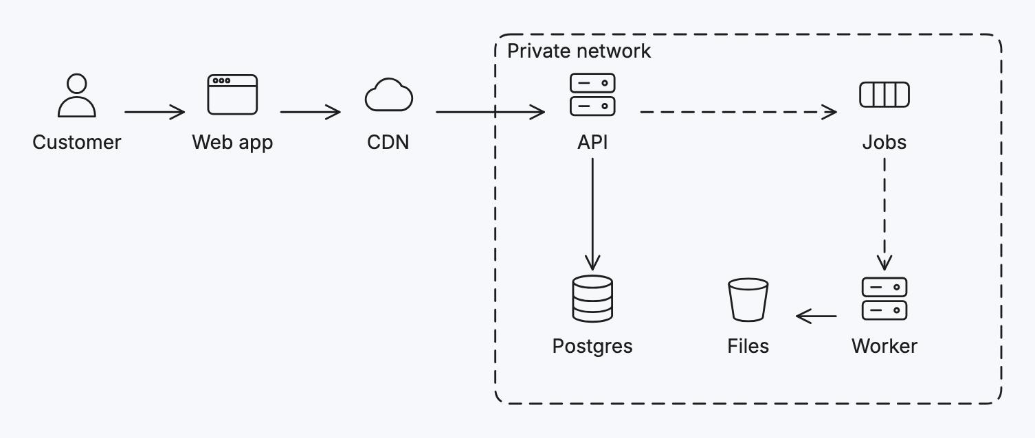
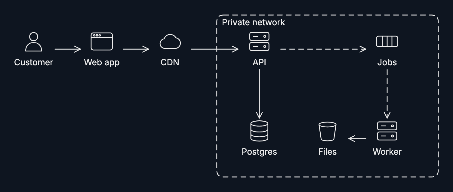
An architecture diagram shows the parts of a system and how they connect: users, apps, servers, databases, queues.
Step by step
-
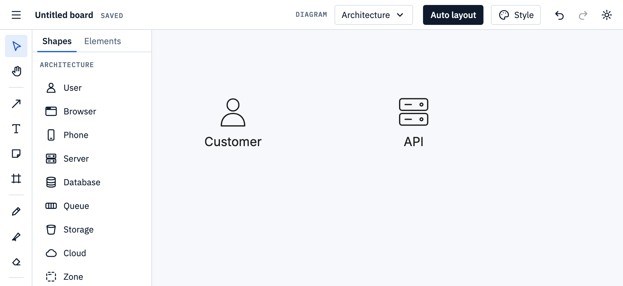
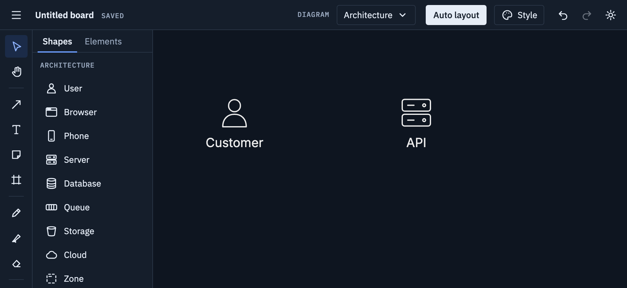
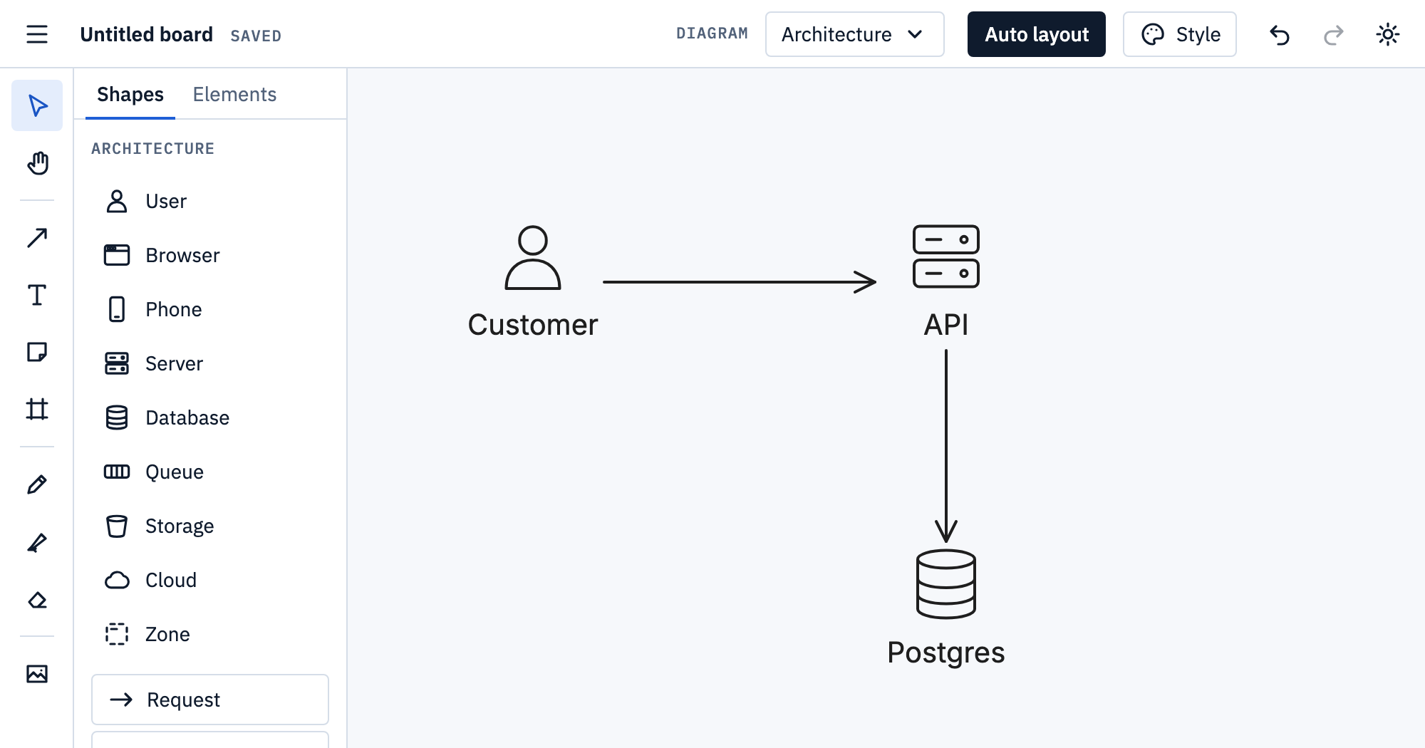
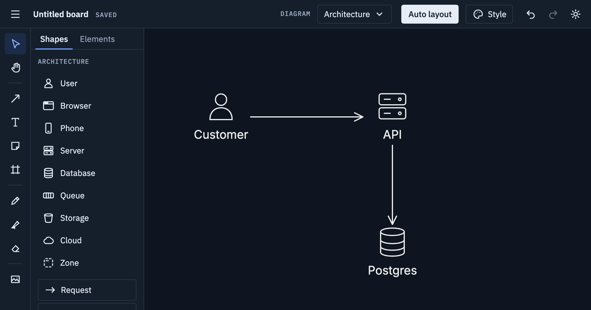
Pick Architecture from the Diagram menu. Place the parts from the panel, like User and Server, and type their names under them.
-
Pick Request and drag from one part to another; add the next parts and requests the same way. Async message draws a dashed one.
-
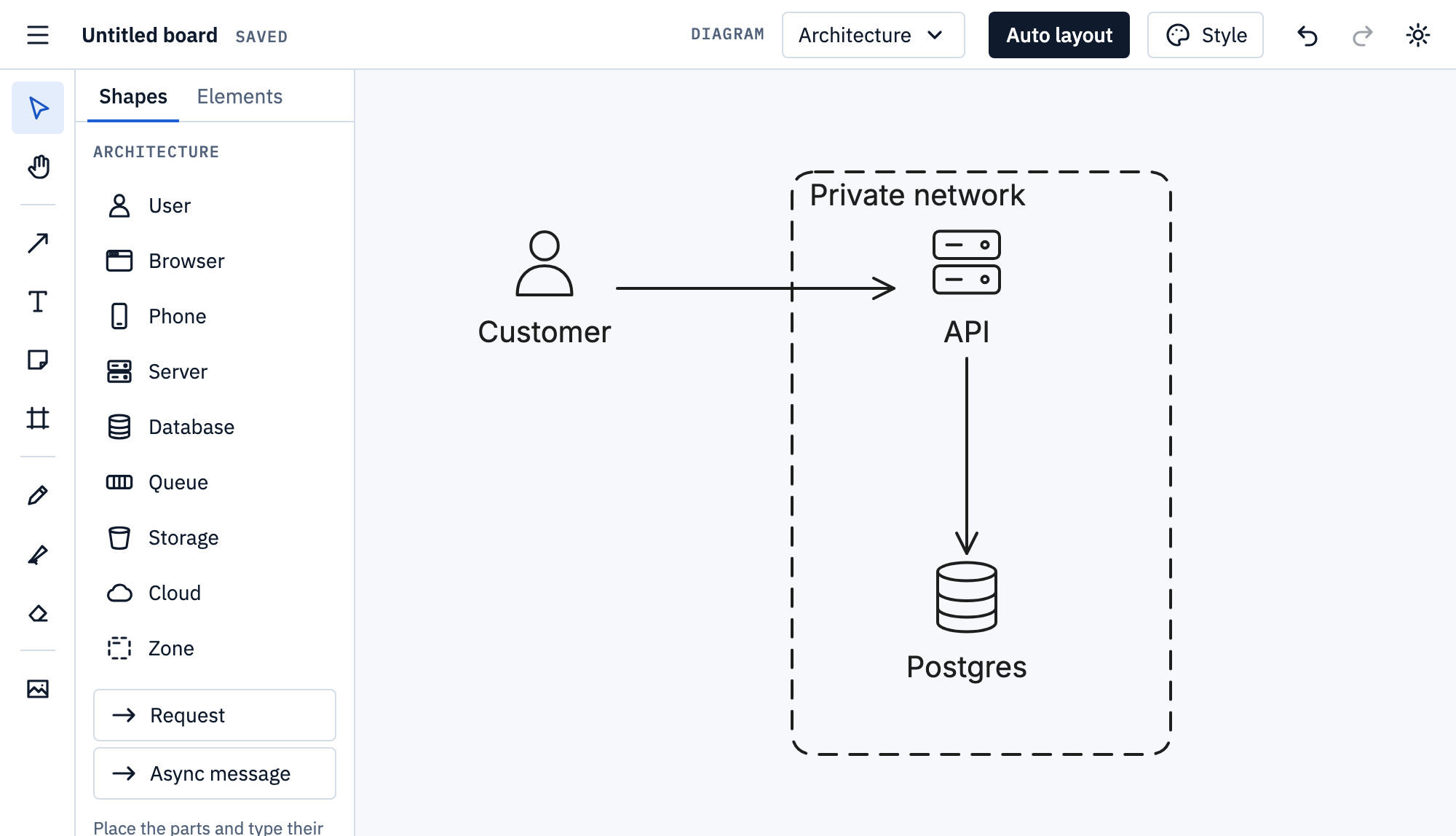
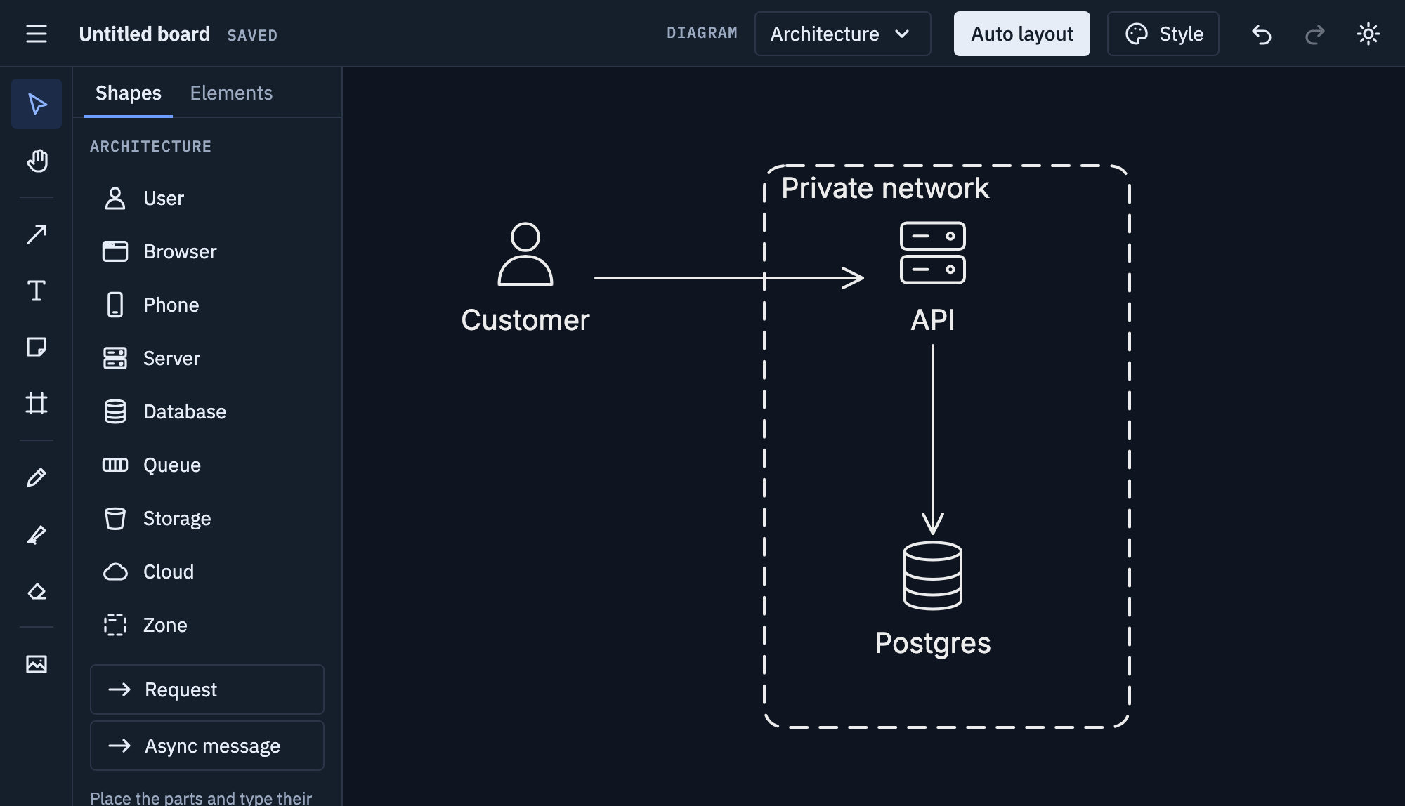
Draw a Zone around parts that share a network, region or team, and name it: what’s inside moves with it.
Tips
- Keep one level of detail per diagram: services, or what’s inside one, not both.
- Use Request for calls that wait for an answer, Async message for those that don’t.
- Arrows point the way requests go, not the way data comes back.
- Beyond servers and databases, the panel has icons for APIs, functions, containers, caches, load balancers, firewalls, the internet, laptops, email and keys (for sign-in).
- Select a part and add a Comment at the bottom of the panel on the right: a note for yourself, like an open question, marked on the board but left out of exports.
Mermaid
Mermaid has no architecture diagram that this app reads; an architecture board exports as a
flowchart, its zones as subgraphs. More on
Mermaid import and export.